The Turbine Supervisory Instrumentation or TSI includes those measurements which monitor the behavior of the rotor train assembly. These include the speed, vibrations, axial position and differential expansion of the turbo set.
What is TSI ?
Turbine Supervisory Instrumentation system which supervises turbine with the help of instruments.
Turbine Supervisory Instrumentation (TSI) Monitors some important parameters which directly or indirectly are linked & predict the healthiness of turbine.
Turbovisory Parameters
Vibrations:-
- Shaft Vibration
- Bearing Vibration
Turbine Expansion:-
- Absolute Expansion [HIP/LP]
- Differential Expansion [HIP/LP]
- Axial Shift
Speed Measurement:-
- Key Phasor
Also Read : Turbine Protective Devices
In order to achieve the purpose of the said measurement indicators, a tap with the world’s trusted manufacturer for vibration monitoring must be carried out, enter Bently Nevada. Tested by time and experience, the Bently Nevada 3500 rack processes the vibrations, axial positions and differential expansions.
Bently Nevada 3500 System configuration
It communicates with the native Turbine Control system via Modbus TCP/IP, through its 3500/92 com gateway card (see Bently Nevada 3500 Rack in detail), in order to display analog figures in front of the Operator Work Stations (HMI).

Figure 1: Typical System configuration of a Bently Nevada 3500 Monitoring System
Trip signals of Shaft Vibrations and Thrust positions are connected in a hardwire fashion from the 3500/32 relay modules to the Turbine Control system which will then demand to shut the solenoid trip block halting the flow of hydraulic oil to the governor and stop valves, closing them on fail-safe action.
Let’s reconnoiter to these aforementioned 3500/xx modules shall we?
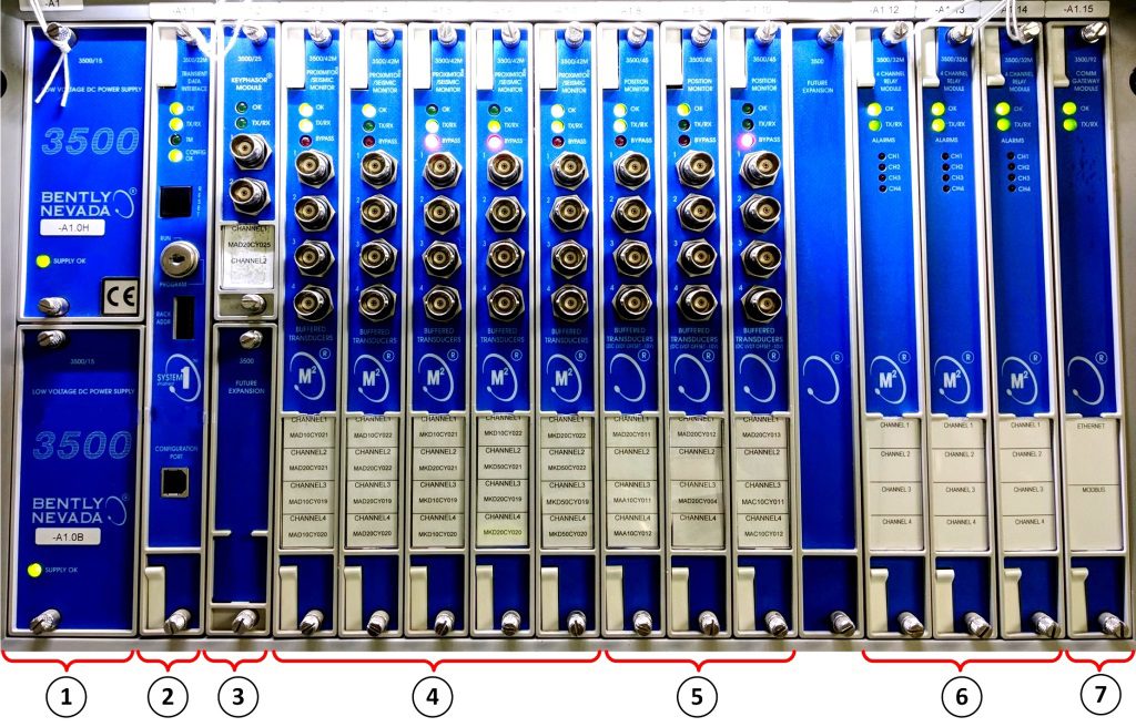
Bently Nevada 3500 Rack in Detail

Figure 2: Actual Installation and Set-up of a Bently Nevada 3500 Rack with numbered labels.
1.) 3500/15 Dual-Redundant Power Supply modules
Half height module (120.7mm) each with the lower card acting as the primary source of power while the other upper card as the secondary (back-up) power.
2.) 3500/22 Transient Data Interface (TDI)
Acts as the interface between the 3500 Monitoring system and compatible software such as System condition monitoring and diagnostics.
TDI interfaces with the M series monitors connected in the rack to continuously collect steady state and transient dynamic data. It also enables each monitor module in the rack backplane to be read and configured by the dedicated 3500 Rack System Configuration Software.

Figure 3: 3500 Rack Configuration (Cfg) Software
3.) 3500/25 Key Phasor
Half height module which receives input signals from proximity probes or magnetic pickups and converts the signal to digital key phasor signals that indicate when the Key Phasor mark on the shaft is under the Key Phasor probe.
A key phasor signal serves as a digital timing signal that is being utilized by monitor modules and external diagnostic equipment to measure vector parameters such as 1X amplitude and phase.
4.) 3500/42M Proximitor / Seismic Monitor
A four channel monitor that accepts input from proximity and seismic transducers, it conditions each signal to generate various static vibrations and position measurements and compares the conditioned signals with user-programmable alarm and danger setpoints.
Each channel can be configured to condition radial vibration, velocity and differential expansion among others.
5.) 3500/45 Position Monitor
A four channel monitor almost similar with 42M in which it also accepts inputs from proximity transducers as well as rotary position transducers and AC/DC Linear variable differential transformers (LVDTs).
Parameters considered as “proportional values” are conditioned from the inputs then compared to user-programmed alert and danger setpoints.
6.) 3500/32M 4Ch Relay
A four channel relay module that provides four relay hardwire outputs. Each relay used on the module can be programmed for an “Alarm Drive Logic” which is composed of AND and OR voting logic for alarm, danger and “Not-OK” statuses. The programming can be executed using the same 3500 Rack Configuration Software to meet the needs of the application.
7.) 3500/92 Communication Gateway
Provides digital communication capabilities of all rack monitored values and statuses for integration with process control and automation systems, the Turbine Control system so to speak. The module can communicate via Ethernet TCP/IP and serial (RS232/422/485) protocols or on top of each other.
Dual Over-speed Racks
Apart from the Bently Nevada 3500 system, a TSI will not be complete without its speed supervising mechanism, enter JAQUET FT3100 rack which has the primary job of assuring that the rotor train’s speed is within limits and shall act when over-speed setpoints occur.
Redundant sensing elements must be installed to make room for frequency control and governing calculations. It can be set-up in such a way that a dedicated set of sensors will be directly wired to the solenoid trip block while the other set takes care of the frequency conditioning function, while still wired to the same trip block.
In this scheme, protection of the rotor train will always be reliable.

Figure 4: JAQUET FT3100 Dual Over-speed Racks Actual Installation and Set-up. The first rack picks-up the sensors for governing calculations paralleled with hardwire trips. The second rack is purely dedicated for hardwire trips.
It has similar set-up with the Bently Nevada except for the fact that its analog function and output hardwire trips are housed within the same module. The analog measurements are sent via 4-20 mA and other digital statuses as hardwire signals.
THE DUAL OVER-SPEED RACKS ARE ALREADY SHIPPED WITH FACTORY SETTINGS MADE BY THE TURBINE MANUFACTURER SO MODIFICATION USING THE FT SOFTWARE IS STRICTLY PROHIBITED AND WILL PASS ON THE LIABILITIES TO US, MAINTENANCE GUYS! I WOULD LOVE TO EXPLORE THE SYSTEM BUT IT MIGHT COST ME MY JOB! I AM NOT SURE WITH BENTLY IF TOUCHING THE SYSTEM JUST TO TAKE BACK-UPS IS STILL POSSIBLE. AT THE END OF THE DAY, IT WILL ALWAYS DEPEND ON THE WARRANTY EXTENT BETWEEN THE TURBINE MANUFACTURER AND THE END-USER.
So far we have only tackled the monitoring systems and have not touched base the sources of information to which these systems are supervising. Now let’s loose the curtains for turbine field instruments and transducers, encore!
Turbine Speed
As mentioned, turbine speed is picked up by probes which measures across a number of shaft gear teeth. A helpful formula when trying to simulate speed by means of a pulse generator will make the statement true.

For instance, take full speed no-load 3600 rpm measured across 132 teeth. The frequency you will be needing to inject is 7920 Hz.
Take note that a certain terminal resistance is required in parallel to each speed acquisition channel. Usually a 1kΩ resistor will suffice.

Figure 5: Illustration of how a set of speed probes is installed with reference to the gear teeth.
Shaft Position
The thrust bearing is a fix point of the shaft itself relative to the casing. The thrust bearing can move axially within its clearances. The supervision of the axial shaft position allows to protect the turbine against shaft displacements caused by excessive thrust rates during transient conditions and disturbances.

Figure 6: Illustration of how a shaft position proximity sensor is installed at a certain clearance.
THE CLEARANCE OF THE PROXIMITY SENSOR MUST BE APPROVED BY THE MECHANICAL GUYS SINCE THEY ARE GOING TO PERFORM “BUMP TESTS.” (HONESTLY I HAVE LITTLE TO ZERO KNOWLEDGE ABOUT THIS PHYSICAL FLOAT CHECK AND BUMP TESTS SO LET’S LEAVE THAT TO THE MECHANICAL EXPERTS.)
Differential Expansion
The axial clearances in blading and shaft seals are dimensioned so that during steady state and transient operation, no rubbing between rotating and stationary parts shall occur. Differential expansion must be supervised at locations where maximum values can occur during disturbances.

Figure 7: Illustration of how a pair of proximity sensors are installed on either the HP/LP bearings to measure expansion differential.
I’LL BE USING THE SAME EXCUSE, THE MECHANICAL EXPERTS KNOW THE BEST METHOD IN ADJUSTING THESE SENSORS AS PER THE UNIQUE CONSTRUCTED CHARACTERISTICS OF THE TURBINE. IT WILL ALWAYS BE A POSSIBILITY THAT TWO SIMILAR TURBINES ON THE SAME POWER BLOCK HAVE DIFFERENT DIFFERENTIAL EXPANSION SETTINGS. US, C&I GUYS ARE JUST ON A SUPPORTING ROLE.
Shaft Vibrations
The duty of the shaft vibration measurements is to detect and monitor changes in the vibrational behavior of the turbine.

Figure 8: A pair of sensors are installed 45 degrees from the identified center line of the rotor shaft. This will constitute the left and right sectional vibration measurements.
Figure 9: The shaft vibration proximity sensor’s clearance must be adjusted according to a linear range of “gap voltage.” This value ranges from -11 to -9 VDC.
Gap Voltage
Figure 10: Actual gap voltage setting as measured from the outputs of a proximitor transducer.
Gap voltage (VDC) is a direct representation of distance between the probe’s tip and the shaft’s surface. This is the quiescent voltage that needs to be adjusted between the proximitor’s output voltage range limits.
Any vibration of the shaft will cause the proximitor’s output voltage to vary in precise step: 200 mV/mil
*1 mil = 1/1000 inch
(As to why it is negative DC voltage in the first place is an entire different story to tell. I might include the legend behind it as this article improves in the future.)
Typical TSI Loop configuration

Figure 11: A complete TSI loop diagram with actual pictures of course!
The proximitor module part of the 3300 XL series provides the required coil excitation to the proximity probe powered by a negative DC source. The proximity probe consists of an encapsulated coil of wire that produces magnetic field in order to induce eddy currents in the metal shaft of the machine. It comes with size variants from 8 to 50 millimeters. At the other end lies the monitor module which, in case you have just skimmed this article, was covered on the first half… part, whatever.
I can again conclude these notes about TSI by showing you a diagram of how the whole Steam Turbine control architecture would look like up to the hydraulic solenoid trip block unit (which I mentioned a couple of times somewhere?) but I decided to set it aside as the battery limit, if you know what I mean. I might include it on the future improvement of this article so fingers crossed!
Editor’s follow-ups: This article was loosely based on materials read by the editor and a bit more by current experience. All published work which may have been contained herein remain to their respective owners. The article is very limited in terms of analyzing what information a TSI gives as this is written from a perspective of a control systems practitioner and not in any way from a vibration specialist or the like. The editor would love to collaborate if some turbine reliability/vibration specialists can come across this article and have their inputs which can help in its content improvement. If the reader has any software requirement that the editor can provide, the editor would be glad to assist through an appreciation comment below.
Bently Nevada is a registered company wholly owned by GE’s measurement and control division.
JAQUET Technology Group was recently acquired by TE Connectivity Ltd. and holds every rights herein.