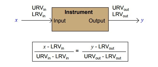
Every instrument has at least one input and at least one output. For instrumentsresponding linearly, the correspondence between input and output is proportional:
PLC Raw Count Calculation

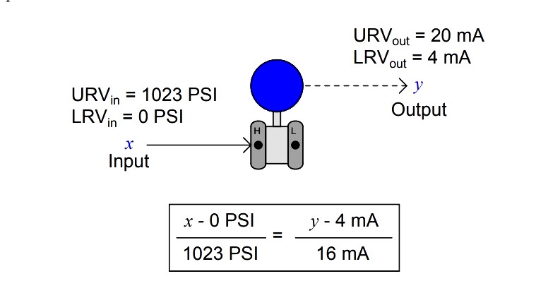
A practical example of this is a pressure transmitter, in this case one with an input range of 0 to 1023 PSI and an output of 4-20 mA

If you happened to measure an output current of 14.7 mA from this pressure transmitter
x = { ( 14.7 – 4 ) / 16 } * 1023 = 684.13 PSI
It would be a simple matter for you to calculate the corresponding input pressure to be 684.13 PSI.
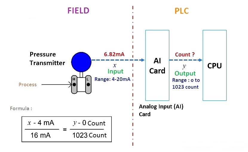
Now consider a pressure transmitter is connected to the PLC system. The pressure transmitter is connected to the Analog input card of the PLC system. The AI card have inbuilt Analog to Digital Converter (ADC). The ADC converts the input 4-20mA value coming from pressure transmitter into equivalent Raw Counts.
The AI card finally sends this Raw counts value to CPU card. The CPU have the pre-defined Pressure transmitter values like its Range (LRV & URV), units etc. The CPU calculates the Process variable (pressure value from pressure transmitter) using these Raw Count from AI card & pre-defined LRV, URV, units etc… and displays the process variable on operator workstations/HMI.
Also Read : Formula to Convert 4-20mA into Process Variable
Take for example this analog-to-digital converter, with a 10-bit output (a “count” range of 0 to 1023) and a 4-20 mA input:

Calculate the corresponding “count” output of this ADC circuit given a 6.82 mA input signal.
Here we are calculating the ADC output in terms of count. So Input to the AI card is “x” and output is “y” as shown in below fig.

y = { ( 6.82 – 4 ) / 16 } * 1023 = 180 count
In a PLC system, CPU converts this count into equivalent Process variable and displays on the operator workstations.


